

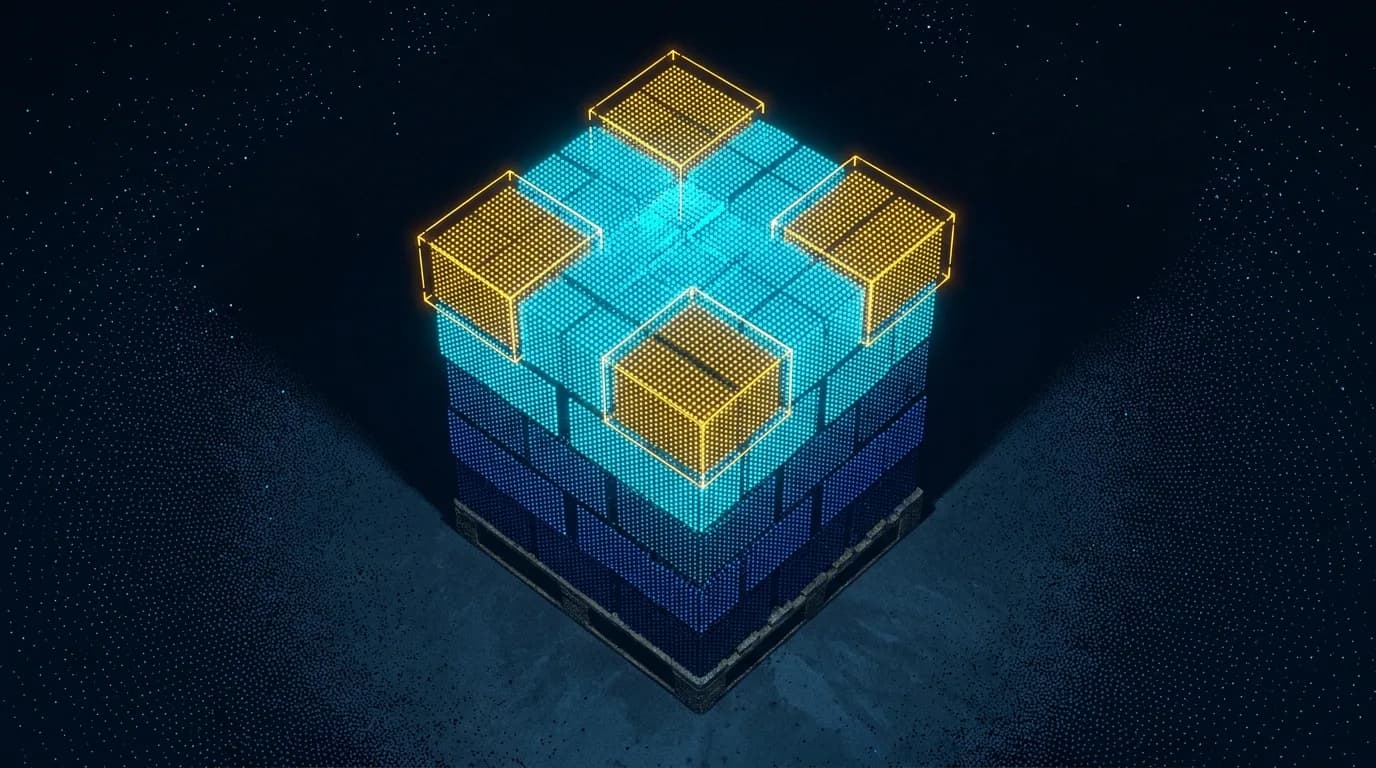
Automated depalletizing is a practical, high-value application for industrial 3D vision. Warehouses, manufacturing plants, logistics centers, and packaging operations need to remove cartons, sacks, bags, and cases from pallets reliably, quickly, and safely. The challenge is that real pallets are not always perfect. Layers shift, packages deform, stacks become incomplete, and product position can vary from pallet to pallet.
A MorpheusTEK-supplied 3D vision-guided depalletizing system helps solve this problem by allowing the automation controller to receive real-time position and pose data from the vision system. The motion sequence may be handled by the customer's controller or automation platform, while the MorpheusTEK vision system provides the perception layer: detecting the pallet, identifying the top-layer items, calculating pick positions, and sending structured data to the controller.
A brand-agnostic system architecture
A MorpheusTEK-supplied depalletizing vision system typically includes three primary control-layer components:
Industrial 3D vision sensor
The 3D camera or depth sensor captures spatial information from above or near the pallet — depth data, RGB data, amplitude data, or a 3D point cloud depending on the application.
Edge vision computer
Processes the 3D data, runs the depalletizing perception algorithm, identifies product positions, and calculates controller-ready coordinates.
Automation controller interface
A PLC, robot controller, industrial PC, or fieldbus gateway that triggers the vision task, receives result data, and coordinates the larger automation sequence.
The engineering focus is the communication path between these layers: 3D vision sensor → edge vision computer → PLC / robot controller / industrial PC / gateway.
What the vision system provides
A 3D vision-guided depalletizing system may provide several types of output to the controller, including:
- Detection result and object center point
- X, Y, and Z coordinates
- Full or partial pose information (roll, pitch, and yaw angles)
- Pick sequence
- Layer height and item count
- Failed-detection status
- Boundary or foreign-object alerts
For depalletizing, one of the most useful outputs is a height-prioritized pick sequence. This allows the automation system to select the tallest or most accessible item first, reducing the risk of collision, unstable picks, or interference with surrounding product.
PLC and controller communication
A MorpheusTEK-supplied depalletizing vision system can be configured to communicate with a PLC, robot controller, industrial PC, or gateway layer. One common method is TCP/IP socket communication using structured data such as JSON. In this architecture, the controller sends a trigger command to the vision computer; the vision computer performs the 3D detection task and returns result and pose data.
- Trigger from controller
- {"action": "3D"}
- Response from vision system
- {"result": 2, "pos": [100, 107.3, 1530, 179, 89, 89, 112, 432.1, 1500, 179, 89, 75]}
The result value indicates whether detection was successful, and the position array provides coordinate and orientation information. Depending on the final system configuration, the data may be provided in millimeters and degrees and mapped into the customer's controller coordinate system.
Communication protocol customization
The documented TCP/IP JSON format should be viewed as one supported communication approach, not as the only possible interface. MorpheusTEK can support customization of TCP-based communication protocols to better match the customer's existing PLC, controller, or plant automation standard.
This flexibility is important because many industrial customers already have preferred message formats, trigger conventions, register maps, and status-handling methods. Rather than requiring the customer to redesign their controls architecture around a fixed vision protocol, the vision communication layer can be adapted to the project requirements.
Direct PLC communication has been implemented in previous depalletizing projects, making this a practical and proven integration pattern. For example, a prior implementation used a compact string-based command and response format where the trigger command selected a detection region and parcel-size configuration:
- Trigger format
- 3D(X)5 — 3D15 = region A, parcel size A · 3D25 = region B, parcel size B
- Response format
- 3DA(X)A(X1)A(Y1)A(Z1)A(YAW1)OK
- No parcel detected
- 3DA0A0A0A0A0AOK
- One parcel detected
- 3DA1A500A600A700A90AOK
- Two parcels detected
- 3DA2A500A600A700A90A50A60A-700A-30AOK
This string-based example is not intended to limit the system design. It demonstrates that the communication layer can be adapted to a customer's preferred format or controls standard. Customers can share the protocol format their controls team is most familiar with, and the system can be adapted accordingly when technically feasible.
TCP/IP JSON vs. traditional PLC protocols
TCP/IP socket communication is flexible and widely supported by many robot controllers, industrial PCs, and advanced automation systems. However, many PLCs are designed around industrial automation protocols such as:
- EtherNet/IP
- PROFINET
- Modbus TCP
- EtherCAT
- CC-Link IE
- CANopen
- DeviceNet
This distinction matters. A controller may have an Ethernet port, but that does not automatically mean it can easily parse JSON over a raw TCP socket. Some PLCs can support socket communication through function blocks or additional programming. Others may require a fieldbus gateway, industrial PC, or controller layer to translate the vision data into PLC-readable tags or registers.
What is a fieldbus gateway?
A fieldbus gateway is an industrial communication translator. It sits between two devices that use different communication methods and converts data from one protocol into another. In a depalletizing vision application, the communication path may look like this: 3D vision system (TCP/IP + structured data) → fieldbus gateway → controller (EtherNet/IP, PROFINET, Modbus TCP, EtherCAT…).
The gateway can translate vision output into controller-readable tags or registers:
- Vision_Result
- 1
- Pick_X_mm
- 100
- Pick_Y_mm
- 107.3
- Pick_Z_mm
- 1530
- Pick_RX_deg
- 179
- Pick_RY_deg
- 89
- Pick_RZ_deg
- 89
This allows the controller to operate in its normal industrial control environment without needing to directly parse JSON.
When is a gateway needed?
A fieldbus gateway may be needed when:
- The PLC cannot parse TCP socket or JSON messages directly
- The customer requires EtherNet/IP, PROFINET, Modbus TCP, EtherCAT, or another industrial protocol
- The plant has approved controls standards
- The integration team wants a clean tag/register interface
- The system must integrate into an existing plant control architecture
When can you skip it?
A gateway may not be needed when:
- The controller can communicate directly with the vision computer
- The PLC supports socket communication
- The customer prefers a customized TCP-based protocol
- An industrial PC is already managing the communication layer
- The controller only requires simple trigger, busy, complete, and fault signals
Practical integration questions
Before selecting the final control architecture, MorpheusTEK recommends asking:
- What PLC or controller brand and model are being used?
- Does the controller support TCP/IP socket communication?
- Can the controller parse JSON, structured text messages, or a custom TCP string format?
- Is there an existing preferred message format, tag map, or register map?
- Is EtherNet/IP, PROFINET, Modbus TCP, EtherCAT, or another protocol required?
- Does the controller need only the next best pick, or a full list of available picks?
- Are discrete IO signals required for trigger, busy, complete, fault, pause, or reset?
- Are there plant standards for approved automation vendors?
- Does the system require safety-rated communication, or only process-level signaling?
Safety and alarm communication
Depalletizing applications can involve shifted loads, damaged packaging, loose debris, abnormal stack geometry, and unexpected objects in the operating area. A 3D vision-guided system can help monitor these conditions by detecting boundary exceptions, foreign objects, and failed-detection conditions. These alerts may be communicated through network messages, digital IO, or integration with stack lights, HMIs, or plant control systems.
Engineering summary
A MorpheusTEK-supplied 3D vision-guided depalletizing system provides the perception layer for automated pallet unloading: an industrial 3D vision sensor, edge vision computer, depalletizing software, and a controller communication interface.
A MorpheusTEK-supplied 3D vision-guided depalletizing system can support controller integration through direct TCP/IP communication, customized TCP-based protocol formats, or a fieldbus gateway translation layer — chosen to fit the customer's controls standard.
The key engineering takeaway
By combining 3D vision, edge computing, controller-ready pose output, flexible communication customization, and gateway options where needed, MorpheusTEK can help integrators and end users deploy practical depalletizing vision systems in real industrial environments.